REX C100 teardown
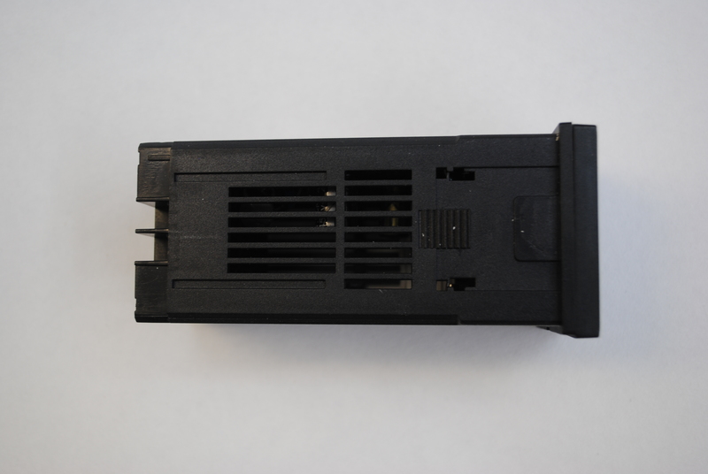
In true eevblog-style we take the REX C100 PID controller and don’t turn it on, but tear it apart.
The controller can be found in many different options on eBay for around 10 Euro. I was curious to see what is inside this cheap PID controller so I opened it up and took some pictures to share.
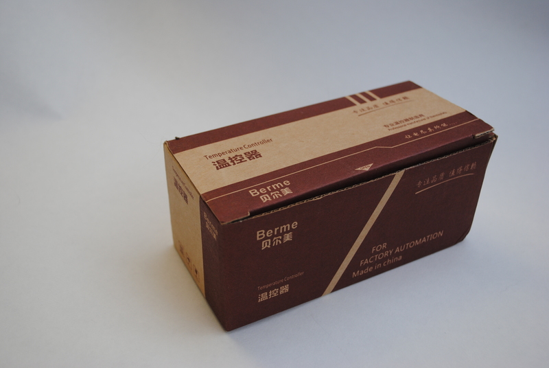
Here’s how you typically find these controllers on eBay.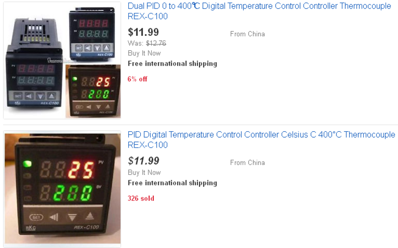
The REX C100 ships in a small cardboard box.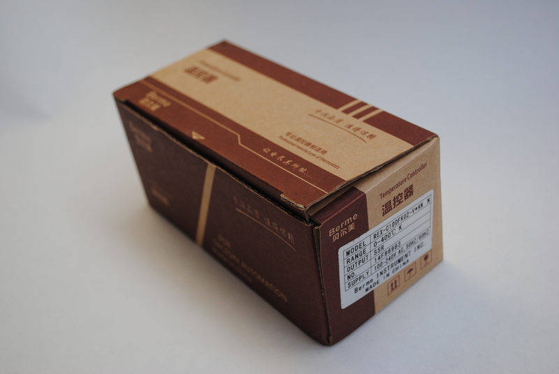
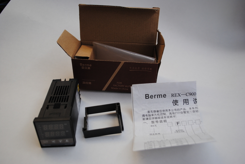
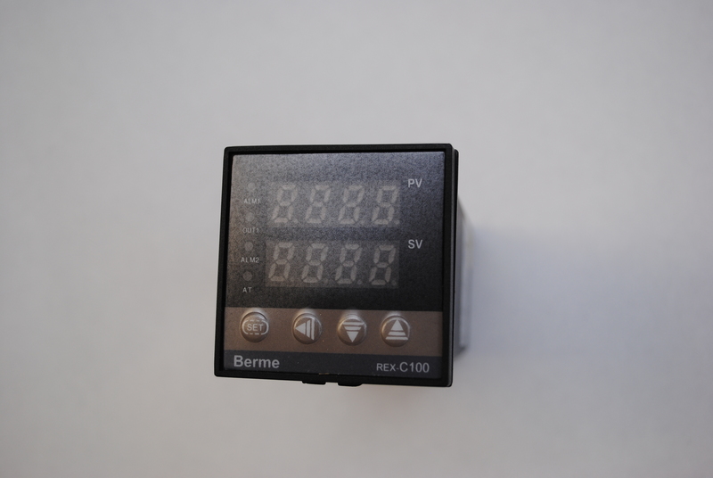
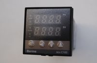
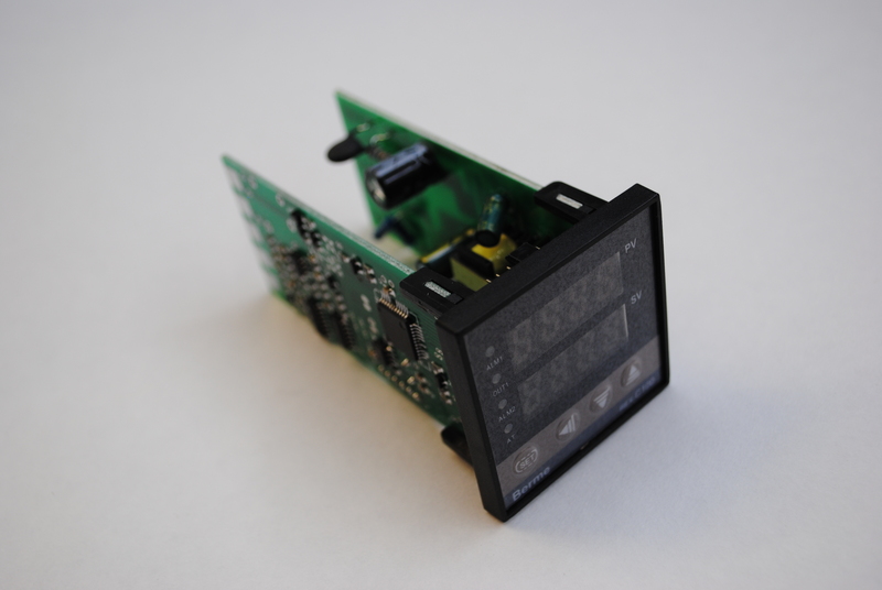
It has 2 4-digit 7-segment LED displays, one for the current temperature (process value or PV) and one for the set temperature (Set Value or SV). Next to these 2 displays are 4 LEDs, ALM1 (alarm 1, if present), OUT1 (output 1 actuated), ALM2 (alarm 2, if present) and AT (?).
Under the displays are 4 buttons, SET , LEFT , DOWN and UP.
The front also has the text “ Berme REX C100 ” printed on the bottom.
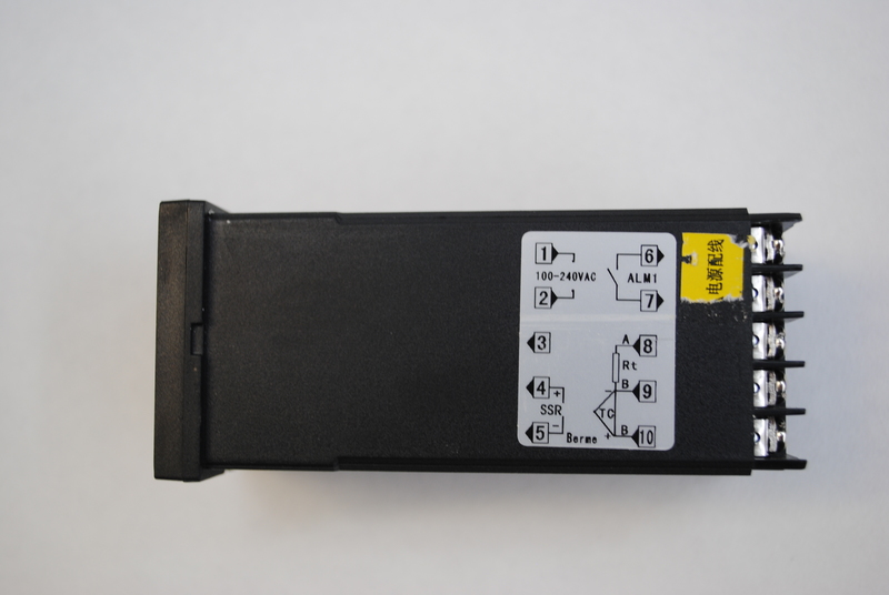
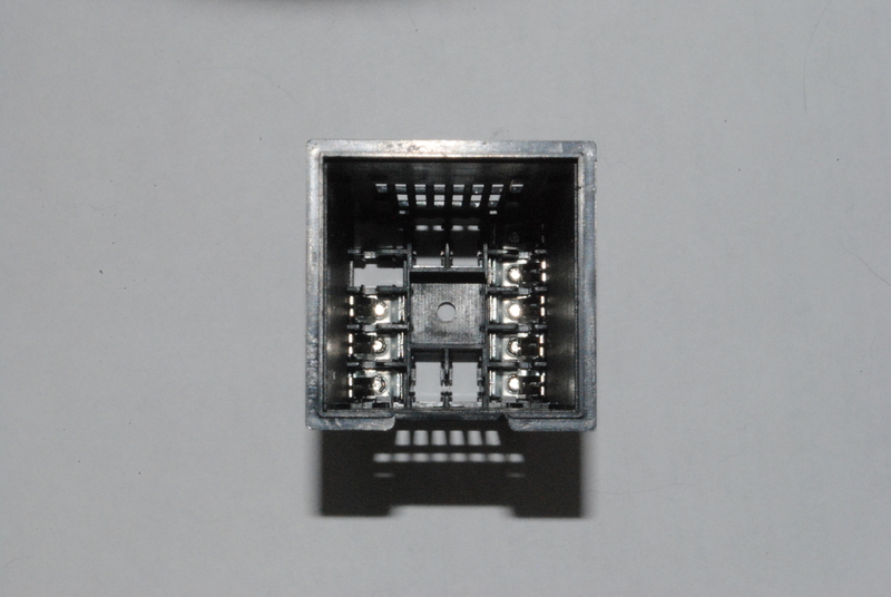
Terminals 1 and 2 are the power input. The unit accepts both 110 and 240V AC power.
4 and 5 connect to the solid state relay (SSR) that controls the output. Mind the polarity here, as SSRs need to be hooked up with the correct polarity.
Terminals 6 and 7 have a dry relay contact for an alarm output.
Terminals 9 and 10 connect to a K-type thermocouple on my version of the REX C100.
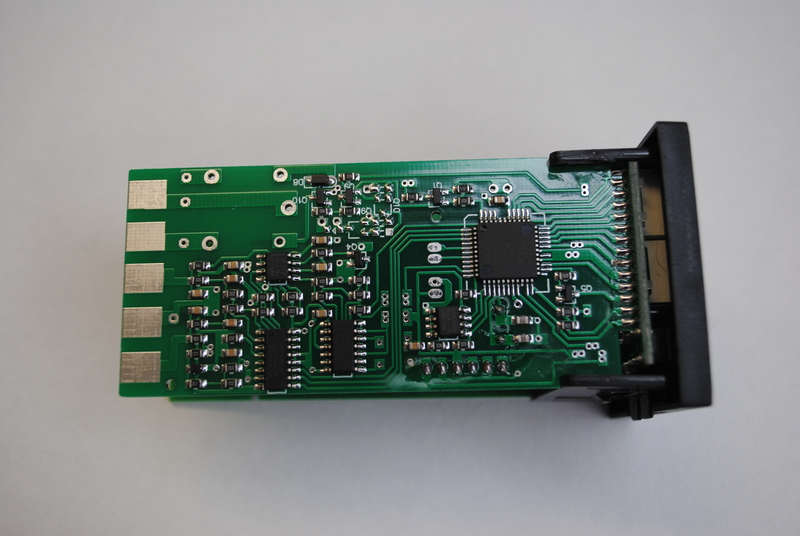
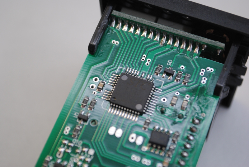
The other chips on the board are:
- 74HC74D: dual positive edge triggered D-type flip-flop.
- HEF40518T: 8-channel analogue multiplexer/demultiplexer, which decodes 3 address lines into 8 outputs.
- LF353: Wide bandwidth Dual JFET Input Operational Amplifier. This opamp is used to measure the temperature using a PT100 or thermocouple.
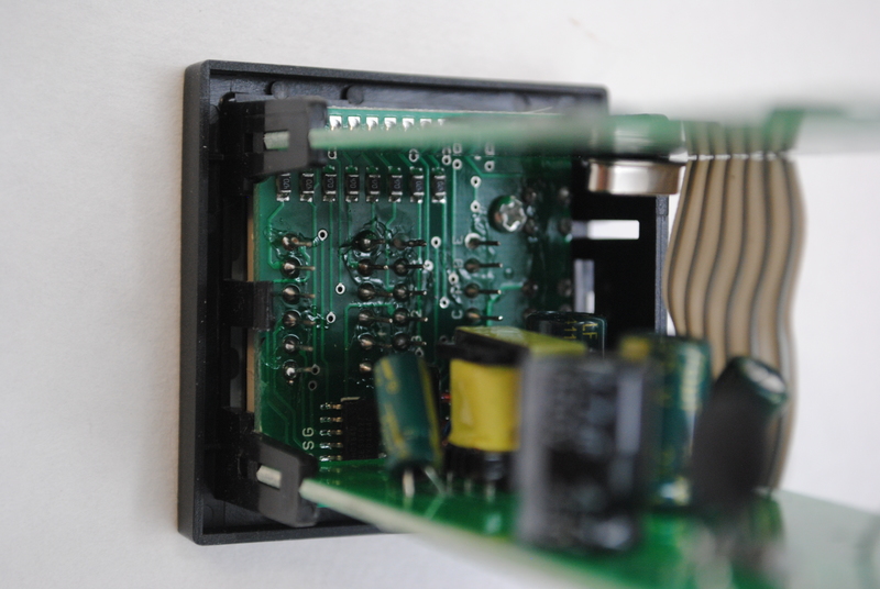
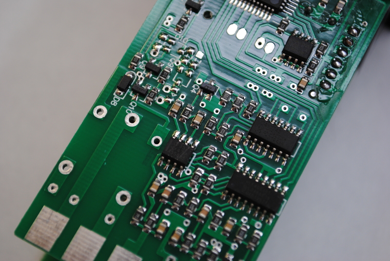
The (unpopulated) rectangular footprint on the bottom left of the picture is for fitting the alarm relay. My REX C100 versions came without the alarm option, so the relay has been left unpopulated. The footprint is marked DC12V on the top of the PCB, so one could get an alarm signal from this footprint. The ground side of the relay is driven to ground through a transistor by the microcontroller in case of an alarm condition.
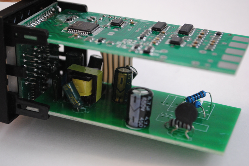
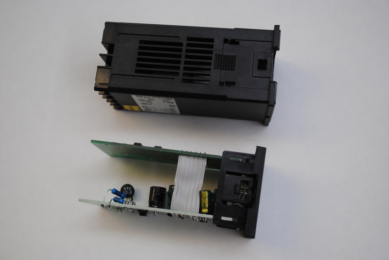
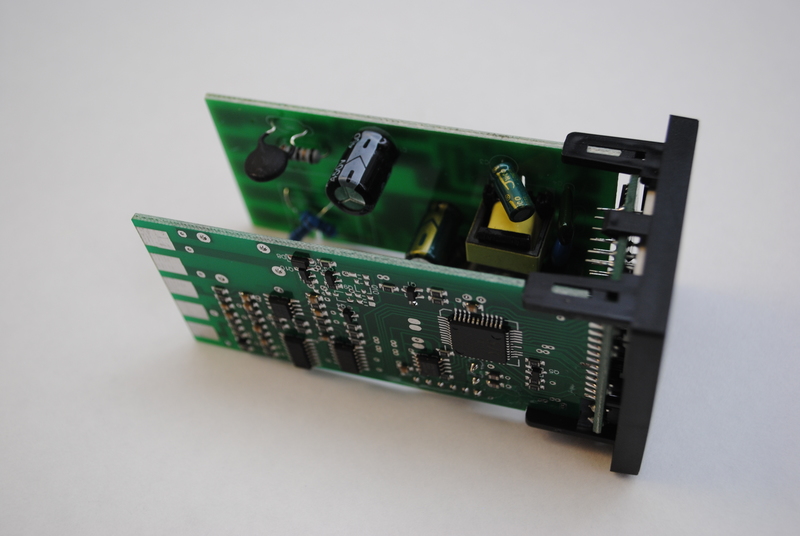
The bottom PCB mostly has a transformer and some caps on the top, and a few SMD components on the bottom. This hints at a power supply PCB.
What is interesting is the two-resistor arrangement on the back right. These resistors are placed over a footprint that can accept either of two different types of PCB-mount relays. The REX C100 PID controller is available with different output options; apparently the relay output versions have a relay populated, and the solid state relay versions have these two resistors to drive the SSR.
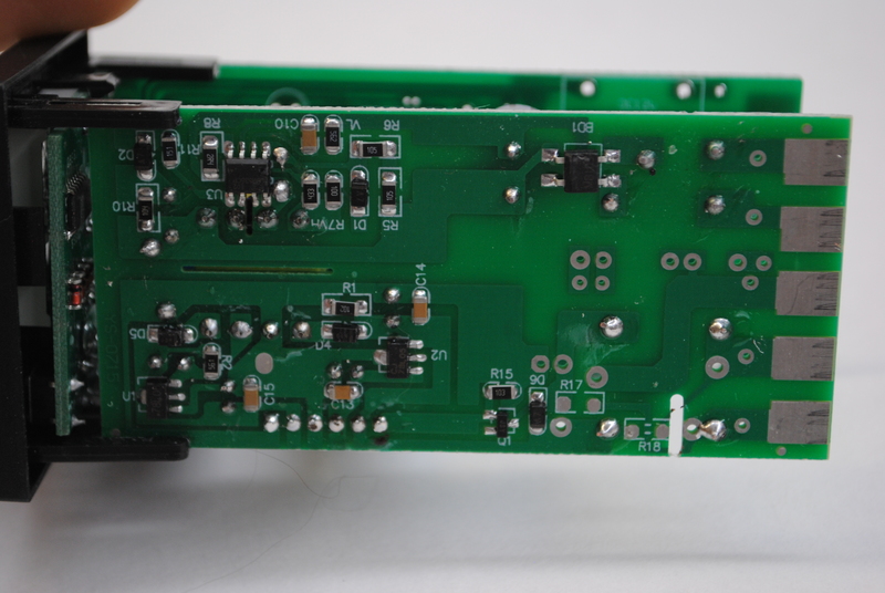
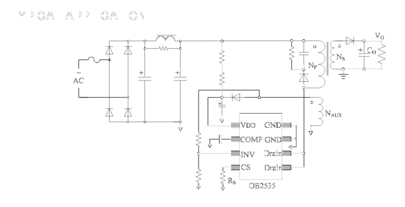
Upstream from the 0B2535CP is a bridge rectifier marked MB103. Between this bridge rectifier and mains power are a resistor and what appears to be an NTC, marked NTC 5D-9 , which apparently is a power NTC thermistor. Funny business. I guess the power supply section is one area where they had to cut costs.
Also on this board are two 78L05 linear regulators.